I have 6 weeks off work now, so im hoping to really get into it over the next little bit!
Showing posts with label Project Black Box. Show all posts
Monday, February 28, 2011
More prepwork
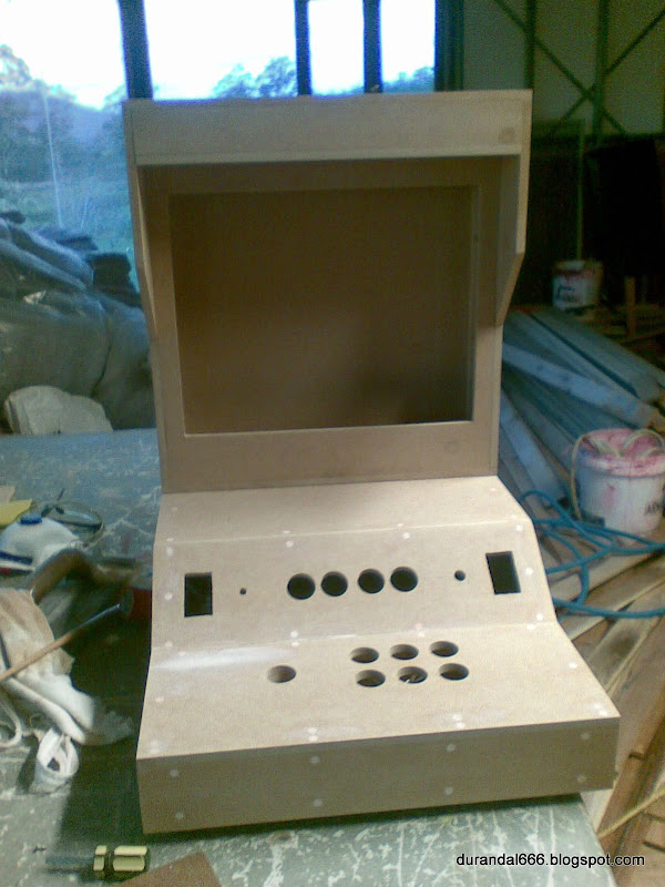
Whelp, a little more work on the Black Box. Not much, but ive bogged the inside in prepration for some more sanding.
I have 6 weeks off work now, so im hoping to really get into it over the next little bit!
Sunday, January 30, 2011
About time..
Finally started sanding the arcade box! Yeah, i know...
Went out and got myself some sandpaper (while I was buying some particle board to extend a old table I got for free from work) and some more bog to fill up the rest of the screw holes. So i got outside and spend a few hours sanding it to size with some 60 grit. The biggest problem has been the top part has a ever so slight bit of play along the piano hinge - which of course means massive variances at the end your playing at. Ive had to sand each side to match the other by putting it on a flat surface and sanding a bit, flip over, sand a bit more, etc. After a while, It's starting to all come together - while the edges arnt perfect yet there a massive improvment as now only a few bits feel raised, where when I started it have a overbite of about 4mm and was a good 1-2mm out on some parts of the side.
Unfortunately im not quite as in-shape as I could be.. After hours of sanding I noticed it was nearly 9PM and the light was gone so I packed up. Pouring a celebratory bourbon, I proceeded to nearly glass myself in the face due to my right arm suddenly responding to all commands by moving about 10 times more than it should have.
Ive done some research and settled on trying to use some decent spraypaint to paint it, after using a automotive putty/primer spraycan. A few goes of the putty/primer (with liberal sanding) should help me really fill in any gaps I have left.
As for colouring, Im still working out what i want to do with artwork.. But im starting to thing black with red lines might be the go (ala a Shivan cruiser.. Damn Shivans...)
Also... ive finially settled on a name. The Black Box, in honor of the phreaking done in the 60's & 70's (shit even 80s I think) - check it out on wiki HERE and even HERE.

Ive also done some work on the VGA->CAT adapters. One of them had its wires tear off their solder joints (damn cheap crap) which I had to re-solder. I suspect it has a lot to do with the bend that it gets internally - i had a right angle adaptor, then the adaptor, then the cable.. and when the lid was closing, it was hitting the cable and bending the whole lot sideways.
So I converted the VGA-CAT adapter itself to right angle mount to save 20mm to avoid this problem in the future. Ugly, yes. Effective, yes.
Went out and got myself some sandpaper (while I was buying some particle board to extend a old table I got for free from work) and some more bog to fill up the rest of the screw holes. So i got outside and spend a few hours sanding it to size with some 60 grit. The biggest problem has been the top part has a ever so slight bit of play along the piano hinge - which of course means massive variances at the end your playing at. Ive had to sand each side to match the other by putting it on a flat surface and sanding a bit, flip over, sand a bit more, etc. After a while, It's starting to all come together - while the edges arnt perfect yet there a massive improvment as now only a few bits feel raised, where when I started it have a overbite of about 4mm and was a good 1-2mm out on some parts of the side.
Unfortunately im not quite as in-shape as I could be.. After hours of sanding I noticed it was nearly 9PM and the light was gone so I packed up. Pouring a celebratory bourbon, I proceeded to nearly glass myself in the face due to my right arm suddenly responding to all commands by moving about 10 times more than it should have.
Ive done some research and settled on trying to use some decent spraypaint to paint it, after using a automotive putty/primer spraycan. A few goes of the putty/primer (with liberal sanding) should help me really fill in any gaps I have left.
As for colouring, Im still working out what i want to do with artwork.. But im starting to thing black with red lines might be the go (ala a Shivan cruiser.. Damn Shivans...)
Also... ive finially settled on a name. The Black Box, in honor of the phreaking done in the 60's & 70's (shit even 80s I think) - check it out on wiki HERE and even HERE.
Ive also done some work on the VGA->CAT adapters. One of them had its wires tear off their solder joints (damn cheap crap) which I had to re-solder. I suspect it has a lot to do with the bend that it gets internally - i had a right angle adaptor, then the adaptor, then the cable.. and when the lid was closing, it was hitting the cable and bending the whole lot sideways.
So I converted the VGA-CAT adapter itself to right angle mount to save 20mm to avoid this problem in the future. Ugly, yes. Effective, yes.
Tuesday, August 3, 2010
The Project again, roadblock gone!
Finally, more work on the project.
Problem:
VGA-CAT5 adaptor works (discussed here), but now the monitor cannot detect that its plugged in. So whats been happening is that every time it changes resolution (pretty much start and end of any game) it pops up that annoying 'ANALOGE MODE' box in the upper left of screen for 10 seconds. Also, when the computers plugged in to power it displays the 'NO CONNECTION DETECTED' box that slides around the screen.
Massively annoying, as its a issue thats only cropped up.
Its taken me over a month to figure out how to fix it easily. Simple answer is splice a VGA cable, but damn I bet that would only cause problems down the track.
Reasoning
I figured that since CAT-5 cable has 8 cables, and VGA has 15 pins, obviously some pins arnt being connected. I also assumed that, since monitors don't display all the crap the moment there plugged into a PC even if its not powered on, it must be something hardwired into the plugs on the computer end that allows the monitor to detect its plugged in even if there's no power on in the PC.
It makes sence that it will run a lower power signal through one pin, and look for a reply down another ground line. But with 15 pins, what combination is correct???
Solution
http://www.monitorworld.com/faq_pages/q17_page.html. This is what got me started on the right track. I noticed on this some 'sense' pins and ground pins - this narrowed it down for me from something like 210 different combination's to try to 9 or so.
I hit on the right one on the second go - shorting pings 10 and 5 made the monitor turn blank ready for input like it used to.
From there it was a simple case of cracking open the cheap CAT-5 -> VGA adaptor and soldering a wire directly across pins 5 & 10. Put back together and re-insert. It was so simple! (Not!)

Creating a short that tricks the monitor into permanently realizing its connected on the analogue mode. Once the shell is fitted back on, its as if i hadnt modded it!
Problem:
VGA-CAT5 adaptor works (discussed here), but now the monitor cannot detect that its plugged in. So whats been happening is that every time it changes resolution (pretty much start and end of any game) it pops up that annoying 'ANALOGE MODE' box in the upper left of screen for 10 seconds. Also, when the computers plugged in to power it displays the 'NO CONNECTION DETECTED' box that slides around the screen.
Massively annoying, as its a issue thats only cropped up.
Its taken me over a month to figure out how to fix it easily. Simple answer is splice a VGA cable, but damn I bet that would only cause problems down the track.
Reasoning
I figured that since CAT-5 cable has 8 cables, and VGA has 15 pins, obviously some pins arnt being connected. I also assumed that, since monitors don't display all the crap the moment there plugged into a PC even if its not powered on, it must be something hardwired into the plugs on the computer end that allows the monitor to detect its plugged in even if there's no power on in the PC.
It makes sence that it will run a lower power signal through one pin, and look for a reply down another ground line. But with 15 pins, what combination is correct???
Solution
http://www.monitorworld.com/faq_pages/q17_page.html. This is what got me started on the right track. I noticed on this some 'sense' pins and ground pins - this narrowed it down for me from something like 210 different combination's to try to 9 or so.
I hit on the right one on the second go - shorting pings 10 and 5 made the monitor turn blank ready for input like it used to.
From there it was a simple case of cracking open the cheap CAT-5 -> VGA adaptor and soldering a wire directly across pins 5 & 10. Put back together and re-insert. It was so simple! (Not!)
Creating a short that tricks the monitor into permanently realizing its connected on the analogue mode. Once the shell is fitted back on, its as if i hadnt modded it!
Sunday, May 2, 2010
More parts
Well, the parts finally arrived so I've been able to get more work done.
What I've imported from China is a VGA to CAT-5 adapter. It was only a few bucks off ebay. This has enabled me to easily pass a CAT-5 cable through the hole between the top and the bottom bit, instead of attempting to splice a proper VGA or DVI cable. I felt this was a much better option.

Right angle VGA adaptor (about 3 pounds from UK delivered) and two male VGA-CAT5 adaptors (about $3AUD from China)
Next up came finally getting all the cables together and getting them to pass between the top and the bottom. I had to get the dremel out with a drum sander attachment and tweak the hole size until it fitted. Wrapping up the cables in some electrical tape was enough to slide it through.

All the top cables taped and slid through the hole. Looks just about right.
Anyway, so the top half's wiring is pretty much complete. My main concern before screwing the lid shut is just doing some real-life testing first, take it to some peoples places, etc. I think I may have to superglue down some cables to ensure I get no cable-rattle.

Top part pretty much done - all the wiring here is done. Just to clean up and fix any rattles/loose cables
Sunday, April 25, 2010
Side panel
Well the side panel is almost done. I spend this weekend attempting to finish it off but every time I went ouside it started to rain, and I prefer not to get electrocuted.
I outlined where everything was to go on paper, cut out a cardboard section to make sure it would all fit, drew that onto the metal and dremel'd myself stupid. Unfortunatly, the USB holes arnt perfect (even after spending about a hour hand-filing them) but they should clean up neat later on.
The panel here is missing a network port. The one I currently have is a bit of a pain to fit well, so I might hunt around for another type.
![]() Layout of the panel | ![]() Work area outside Work area in the BBQ area |
![]() Side panel dummy-fitted into project | ![]() Testing out the plugs |
Project Addition?
Mate sent me a link from hackaday (Thanks murph) - a guy that built a small usb plug-in multi-video-games-system that plugs into a computer and allows you to play emulated games via the authentic controllers (Link)
Now, considering ive already planned to use that 15-pin adapter linked up to the I-Pac, why not do the same for the project.
In this light, I have started looking around for original controllers to slowly start buying up.
Also, check out his arcade room! (Link)
Now, considering ive already planned to use that 15-pin adapter linked up to the I-Pac, why not do the same for the project.
In this light, I have started looking around for original controllers to slowly start buying up.
Also, check out his arcade room! (Link)
Thursday, April 8, 2010
Audio again?
Ok, so I haven't finished with the audio. I realized I hadn't done the last part - support for external audio.
Playing on the jukebox made me realize just how bad the speakers sound for actual music. I would much prefer to have support for external audio. This will mean a additional cable from the top to the bottom, but I think its worth the effort.
So today I have unsoldered the Line Out adaptor and ran another extension cable for it, so that i can put a Line Out in the bottom . To test this, I whipped out my trusty alligator cables and tested it out. After a bit of fiddling, I have a working Line Out jack that disables the internal speakers when a external source is connected.

Working trial of the external jack - disables internal speakers when external audio is plugged in.
Wiring win!
Tested out the 240V wiring that I completed last year. I was waiting for the sparky at work to continuity check it, but every time I brought in the project he wasnt there, every time i didnt he was there, and now hes on holdiays in New Zealand. Dammit.
So I continuity checked it myself twice, double-checked the whole circuit, ensured all points were well and truly insulated, and plugged it in. First with no load, second with the speaker powerpack plugged in, third with the monitor included, and fourth the whole thing. It worked perfectly.
Please note: DONT TRY THIS AT HOME. GET IT CHECKED BY A QUALIFIED ELECTRICIAN, OR EVEN BETTER, DONE BY A QUALIFIED ELECTRICIAN.
Now that im not suffering from a bad case of death, its onward to other areas of improvment.
Tuesday, April 6, 2010
Audio circuit round #3
"Today I have debugged the sound system (Lost a channel of audio, pulled the whole thing apart and later found it was the wire snapped off its solder on the audio circuit, and was stuck in place with the plastic so I couldn't tell it had snapped), got the 240V wiring done, and finialized the audio circuits." - Nat Allan, Jan 24, 2010.
Audio finalized? Bwahaha, what a idiot.
Over the last 3 days I have struggled with the audio stuff more. I had massive trouble extending out the potentiometer for the volume control... When I did so, the voulme got jammed at maximum and moving the volume knob just tuned RADIO STATIONS. Immensely frustrating, even if i did manage to get the footy scores.
Of course, not only did the potentiometer turn out to be broken, but some moron who will remain nameless used single wires from a roll he had to extend the volume pot, not sheilded audio cable he specifically bought for that exact purpose.

Braided single core wire mixed with audio = fail.
At jaycar, I bought (Amogst other stuff I didnt specifically need of course) a A10K Double-Gang potentiometer. The old one was linear (B10k) but I decided to try out a logrithmic pot, as they are supposed to be 'correct' for hearing (as human hearing works on a log scale as well). Unfortunatly, ive found this computer speaker amp hits a comfortably loud volume at 1K ohms, so having a 10K pot is overkill anyway.

Working temporary rig with cannobalized 50k pot from spare parts. The Project was playing a random SNES advertisment at the time, and as i took the pic it summised my feelings on finially getting it working.

Working log scale double-gang pot. Hooked it up temporarily with alligator clips to ensure I had it marginally right.
Above, you can see ive purchased spare alligator clips (Sooooo handy). When I was trialing with the pots earlier,l i only had 2 alligator clips, so i spend hours soldering and unsoldering when it didnt work. Big pack of alligator clips pre-made at Jaycar for $11 bucks has already saved me hours.
In non-audio news, ive also wired up the 80mm case fan mounted in the top of the box (to help remove heat from the monitor/sound adaptor. This has been directly wired into the DC input of the audio board (dammit, go away audio). I thought this would be a terrible idea in terms of noise on the audio's power line, but it makes no audiable difference. I did have to wire in two 100ohm resisters into the cable however to trim back the fan speed as it was two loud. These i wired in parallel to get a resistance of 50ohm (I think thats how the maths goes) as i couldn't be bothered finding a 50ohm resistor in my spare box when i had two 100's in front of me. Below the resistors are spliced in-line under the green shrink-tube.

Two 100ohm resistors wired in parallel on the top fan's power to bring down the speed to keep it nice and quiet.
Sunday, January 24, 2010
Sound
Well, Ive done a little work on the sound circuit as shown below. Since ive removed the variable resistor from the circuit and basically added a extension cord, ive had to make up a bracket for it

Sunday, January 3, 2010
Work continues
Well, now its coming up on a year of being going, sigh. Epic Project.
Today I have debugged the sound system (Lost a channel of audio, pulled the whole thing apart and later found it was the wire snapped off its solder on the audio circuit, and was stuck in place with the plastic so I couldn't tell it had snapped), got the 240V wiring done, and finialized the audio circuits.
I decided to put the audio circuit in the top part of the box, to help de-clutter the base. This will mean more wires needed to run to the base (as the volume control variable resistor requires 5 wires) but will easily fit.
![]() New workplace | ![]() Mains circuit complete |
![]() Mains wiring halfway | ![]() Audio circuit finished |
Saturday, December 5, 2009
Move
Well, as with all things, the upsides are balanced by downsite.
Upside: New Place is awesome
Downside: Spare parts box has become dangerous
Upside: New Place is awesome
Downside: Spare parts box has become dangerous

Tuesday, November 17, 2009
Status: On Hold
Unfortuantly, due to the following factors The Porject (sic) (tm) has been delayed:
The project will re-commence work shortly after i sort all this out.
- Coming into the busiest time of the work year
- Requiring additional surgery
- Having the owner of my unit sell the place from under me with bugger all notice
The project will re-commence work shortly after i sort all this out.
Tuesday, September 1, 2009
IT LIVES!
Yeah, I couldnt wait, (Plus the guy whos painting it is coming over Friday to see what im describing) so i re-fitted it together. Then went a bit mad with double-sided velcro and velcroed the speakers in and the monitor in. End result, is very very much what it will be like.
What a blast to play on.

What a blast to play on.
Sunday, August 30, 2009
Can you splice a DVI-D single channel cable?
YES YOU CAN. WHEE. Yep, that mishapen lump is the splice in the DVI cable I did with just twisting wires and duct tape, and yes, that's the actual cable the monitor is running of. Ill call her Frankensplice.
Well, at some point I had to face splicing a monitor cable. I was going to use VGA, but i found a old DVI-D cable lying around. I never saw the difference in image quality so it ended up in the magical box of spare cables.
However, I decided to research the difference for this project (as the video card is DVI out and the LCD supports VGA and DVI input) and found one massive surprise: While I really couldn't see the difference in quality on the LCD (as I believe newer LCD's are very good at converting the analogue VGA signal) I did notice one thing: The scaling and repositioning of the screen was gone.
Under VGA, the screen has to detect where and how to fit the screen, resulting in it flickering on and off, changing in size and sliding around to fit. This was annoying on my test runs as it happened going into each game, and sometimes (5-10%) it wouldnt get it right and slide the screen a centimeter to the left, obscuring part of the screen.
DVI DOES NOT DO THAT. It displays the image crisp and clear, no flickering and always in the right position instantly. I didnt know this beforehand!
So it had to go in. Question was, was it possible to splice the cable without signal degredation? I have to fit the cable through a loom tube (just big enough for the cables between top and bottom), I certaintly couldnt get the connector through. Downside was, this cable is sheilded with tiwsted pairs, and removing these for a splice has a risk of interupting data, much like untwisting CAT-5 can make the cable less than optimal in use.
What was more fun: Not only did it look scary enough when I opened it up (four pairs of sheilded wire, with 5 lying speerate = 13 cables), but when I got into it i found a third uninsulated wire inside each of the four shielded pairs (4 times 3 + 5 = 17 cables!)
So I had a go as a trial run before the real deal next build time, and I got it right the first time without solder or heatshrink. All I did was twist the wires and insulate with duct tape. Little help sourced from this thread: http://www.avrfreaks.net/index.php?name=PNphpBB2&file=printview&t=44543&start=0.
Im going out tommorow to invest in some heatshrink and a small blowtorch for the real deal, which will be done with a lot more precision in care. This was just the test run, proof of concept to ensure I could actually do it.
Thursday, August 27, 2009
Speaker Epic Deveat
The speakers I had installed seemed like epic win. They fit well and cranked out some tunes from my Ipod. Or so I thought.
It wasn't until later I unplugged my Ipod and plugged it into my PC. The noise. Oh the noise. I thought having it plugged into the running PC and into my Ipod was a good test. Apparently not. It had the most horrible line noise ever. So that USB speaker idea went in the bin after hours of trying to fix it. EPIC DEVEAT.
So I ended up going back to my old 2.0 powered speakers, which are working even better.
Deveat (Verb): Something that seems like complete fail, but has a hidden win.
Antonym(s): See VICTOLY
So Ive had to redo the speakers with a powered set. The sound quality is much improved, with NO LINE NOISE. Huzhaa.
Ive also completed the top wiring in terms of 240V power. I had to use a junction box and split of another mains for the powerpack for the new speakers.
Ive also done some work on the Jukebox side of things, and neatend up the playlist (also got something for all the album artwork)

EDIT: My first Bubble Bobble Million.
It wasn't until later I unplugged my Ipod and plugged it into my PC. The noise. Oh the noise. I thought having it plugged into the running PC and into my Ipod was a good test. Apparently not. It had the most horrible line noise ever. So that USB speaker idea went in the bin after hours of trying to fix it. EPIC DEVEAT.
So I ended up going back to my old 2.0 powered speakers, which are working even better.
Deveat (Verb): Something that seems like complete fail, but has a hidden win.
Antonym(s): See VICTOLY
So Ive had to redo the speakers with a powered set. The sound quality is much improved, with NO LINE NOISE. Huzhaa.
Ive also completed the top wiring in terms of 240V power. I had to use a junction box and split of another mains for the powerpack for the new speakers.
![]() Re-done speakers. | Testing the junction wiring |
Looks safe | Completed wiring |
Ive also done some work on the Jukebox side of things, and neatend up the playlist (also got something for all the album artwork)
EDIT: My first Bubble Bobble Million.

Monday, August 24, 2009
Day 5 (?) Casebuilding
I think Ive missed two days. Oh well.

Case sat together in its closed position

Case in the open position
Another day of work brought us to this. The top part is assembled, and just needs the speakers and LCD put in.
The word of the day was DREMEL. I used it a lot, for sanding out slots for the speakers and LCD, to cutting the mounting out of the speakers (As we couldnt just screw the speakers to the wood)
As for the speakers, I had to sand out some of the pine reinforcment to fit the speakers.
We also got the LCD fitted (but not mounted) at this point.

Case sat together in its closed position

Case in the open position
Another day of work brought us to this. The top part is assembled, and just needs the speakers and LCD put in.
The word of the day was DREMEL. I used it a lot, for sanding out slots for the speakers and LCD, to cutting the mounting out of the speakers (As we couldnt just screw the speakers to the wood)
As for the speakers, I had to sand out some of the pine reinforcment to fit the speakers.
![]() Speaker mount removed from casing | ![]() Hole cut and sanded out |
![]() Mounts glued in place with liquid nails | ![]() Speakers mounted |
We also got the LCD fitted (but not mounted) at this point.
![]() LCD from front | ![]() Dremel line where we had to sand back the pine to fit the LCD |
Saturday, August 22, 2009
HIGHSCORE! Wait, whered it go?
Alright, long delay between updates as I havent had access to the WIP case. Between my mate going to QLD on business for two weeks, and upon his return going in for surgery, I have had little time to get out and work on the case. Since I have now spent two weeks only able to lie down and either watch Stargate or play Eternal Sonata on my PS3, I've gone half mad and decided to set up The Projects components in a old computer case and tinker with the software/hardware.
Ive picked myself up a Dremel 300 from Bunnings and a few extra bits for it from Jaycar, along with a peice of sheet steel from Bunnings. This will enable me to cut out some of the finer square holes/etc out of the sheet, which was posing a problem (cutting out 30mmx 25mm square out of 6mm sheet steel would be difficult with a standard tool) I shall do some work on this tomorrow (as tomorrow it is when I shall be next working on the case, wound or no wound)
Ive also done some work on the software, mainly MAME. Ok, so by 'Work' I mean playing Bobble Bubble for a while (and still only a maximum of level 32 on Easy starting with 5 lives). However, one thing I have done is re-enable High Score saving for games in MAME.
MAME's goal is to achieve 'perfect' emulation of cabinets, or as close to it as possible. Also, many MAME games did not save High Score tables. This is due to the original games not saving the high score in their firmware. Why? Because most arcade ops back then would have left them running for weeks or months on end, meaning that saving the high score table was not really a issue. This meant on power-down high scores were lost, and when you quit mame and start again its the same as a power-down. There is a autosave feature in MAME, but who wants to start up MAME and find themselves halfway through a game they rage-quitted?
MAME devs patched in a hack of saving high scores into MAME for a while (somewhere in the originals 0.60 -> 1.03 region from memory) but then removed it as it was causing more problems than good. Their goal was to recreate the original hardware, not add features.
Of course, someone had to add it back in for people like us. MKCHAMP over at the BYOAC forums was that person, who has released patches and compiles of newer MAME vers with the old highscore saver enabled. I found a highscore enabled MAME compile and matching highscore.dat file here (http://highscore.mameworld.info/)
Ive installed and tested it - works a treat for all the games ive tested (ok, ive only tested one, Bubble Bobble). Thanks guys!
Ive also got myself a very cheap pair of USB powered speakers for the box (http://www.jaycar.com.au/productView.asp?ID=XC5191&keywords=usb+speakers&form=KEYWORD) which should be excelnt for the box (Analogue volume control and no clunky transformer for power [The more expensive ones all had digital volume, which isnt what I want])
Monday, July 20, 2009
More vids
Uploaded these a while ago, hadn't got around to updating.
Tuesday, July 7, 2009
Day 4 Casebuilding
Alright, forgot to well, update after the last day. Mainly because Rod has visitors and not really anything was done, except I bogged the hell out of the box. And the ending of BSG did make me shit myself.
Note to self: Really really really don't use much hardener.

Builders version of Clerasil
We started cutting out the parts for the top the last time I was down. Unfortunately, i didn't take and shots of it. Although, i did have to strip down the monitor too see what size it would fit into, and I decided to fire up the pc stripped down to see if there was any more viewable area behind the plastic (there wasn't)

Firing up the pc stripped
Around about here I was permanently banned from sanding, as I had sanded so much that I sanded out the bog id meticulously put in, and I've sanded back the dimensions from 400mm wide to 399mm wide, making fitting the top part harder.
At this point I'm out of project pictures, so heres a picture of a little kitten. This is the latest addition to their household. His favorite hobbies appear to be eating, sleeping and chasing toys.

Subscribe to:
Posts (Atom)